1. The shape above the PCB
A good starting point when calculating PCB connector stacks is to calculate the board-to-board connector height. This is the measurement from the printed circuit board surface to its highest point on top of the PCB, called its profile. See below for some examples:


2. Parallel PCB Mating – Height Connectors
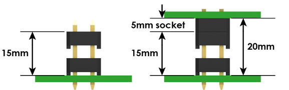
When precise distances between PCBs are required, stacked pins and female sockets are often used in conjunction with the design.
For example, if a PCB separation distance of 20mm is required, a 5.00mm profile receptacle with 15mm stack height rise pins could be used. This is just an example as we have connectors in the J&B board to board range with various plastic sizes depending on the connector pitch.
Please note that the 1mm board to board poly core is not suitable for load bearing applications. The cores should only be used to aid pin alignment and it is recommended that additional mechanical support is provided for the PCB. J&B can provide a load bearing solution if required, please contact us to discuss the best solution for your application.
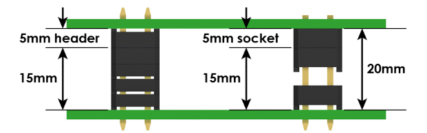
3. Parallel PCB Mating – Raised Sockets
Alternatives to Multi-Plastic. Why Customers Choose Multi-Plastic Line Pins:
- Isolation-protection contacts.
- Stacking solutions are required – the design of PCB connectors is not under the control of the customer. Examples include off-the-shelf wireless module PCBs.
- Higher strength compared to stacked female chassis.
- If two stacked designs are used, an open-height connector and socket will be polarized.
4. Parallel PCB Mating – Bottom Entry Sockets
Also known as a straight-through, it allows matching to the row of pins from the bottom side of the PCB instead of the top side.
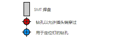
When using the bottom entry socket, drill holes in the PCB to allow the row of pins to pass through.
Example of bottom entry, SMT socket PCB layout: